Waveform Generation
Analysis of other Stan Meyer waveform generation means. 9XB, 9XA, 10XA, Adjustable PWM
- 9XA Generator
- Adjustable Pulse Width Gated Frequency Generator
- 9XB Generator
- 10XA
- CD4046 Phase Lock Loop Gated Frequency Generator
9XA Generator
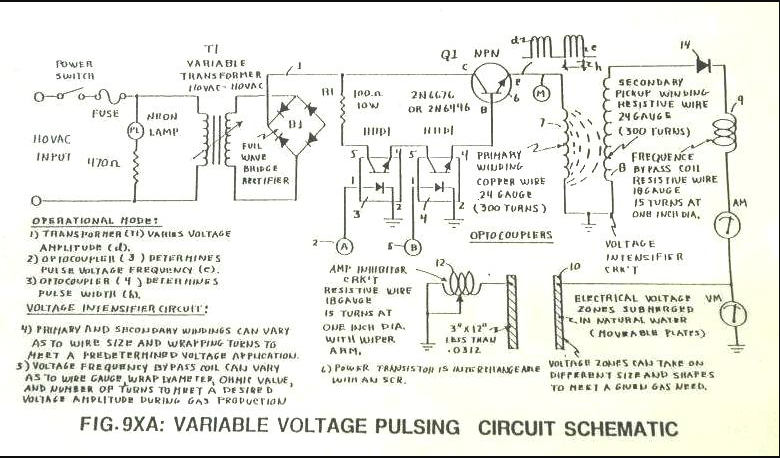
The 9XA was a circuit that Stan used to produce a gated pulse frequency via two H11D1 optocouplers. The optocouplers were driven by two independent stages of 555 timer clock frequency into 3 7490 decade counter ICs. The 7490s provided divisions of 555 frequency, but also produced 50% duty cycle pulses. Below, "A" is one 555/7490 stage and "B" is second 555/7490 stage. The two optocouplers produce an equivalent to AND logic gate.
Figure 1: 9XA schematic
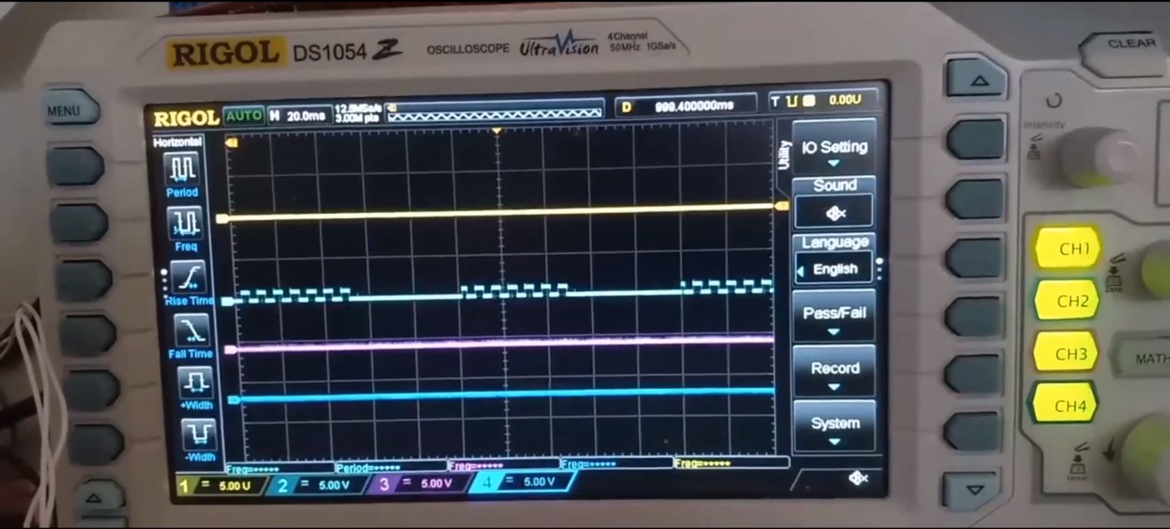
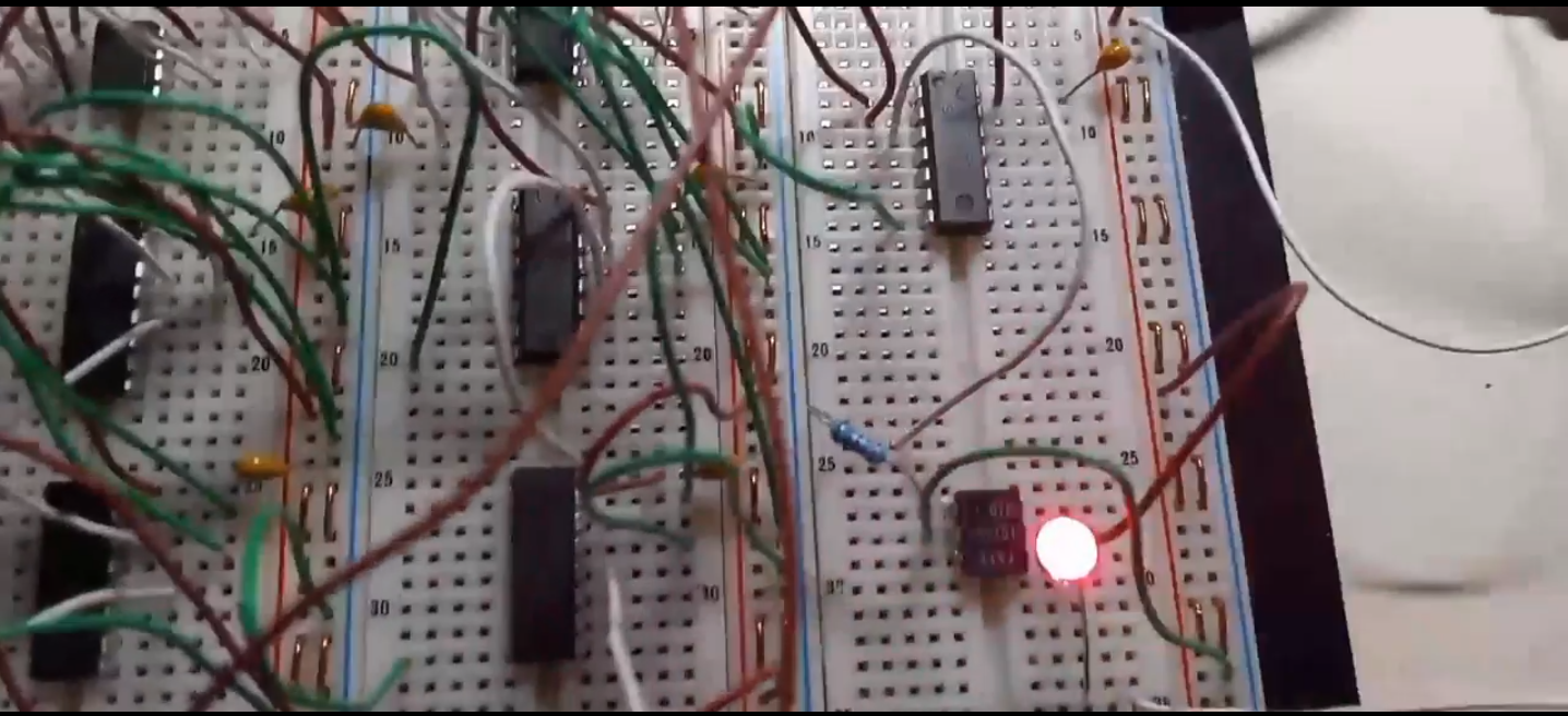
Below is an 9xa scope shot, showing how two independent 9XB style frequency generator's outputs were used to trigger two H11D1 optocouplers to produce a gated pulse train as shown in schematic. In this setup, I had 555's produce a 100khz output to 4 CD4017 dividers. This allowed a 10khz with 50/50 duty cycle to be achieved. LED is just for visual confirmation. If looking closely, you can see how the gating generator isn't synchronized with frequency generator. This causes extra pulses to arise during gated ON times, also called "clock drift".
NOTE: CD4017s were used in place of 7490s, they accomplish the same task with less wiring required.
Video Link: 9XA Circuit Waveform
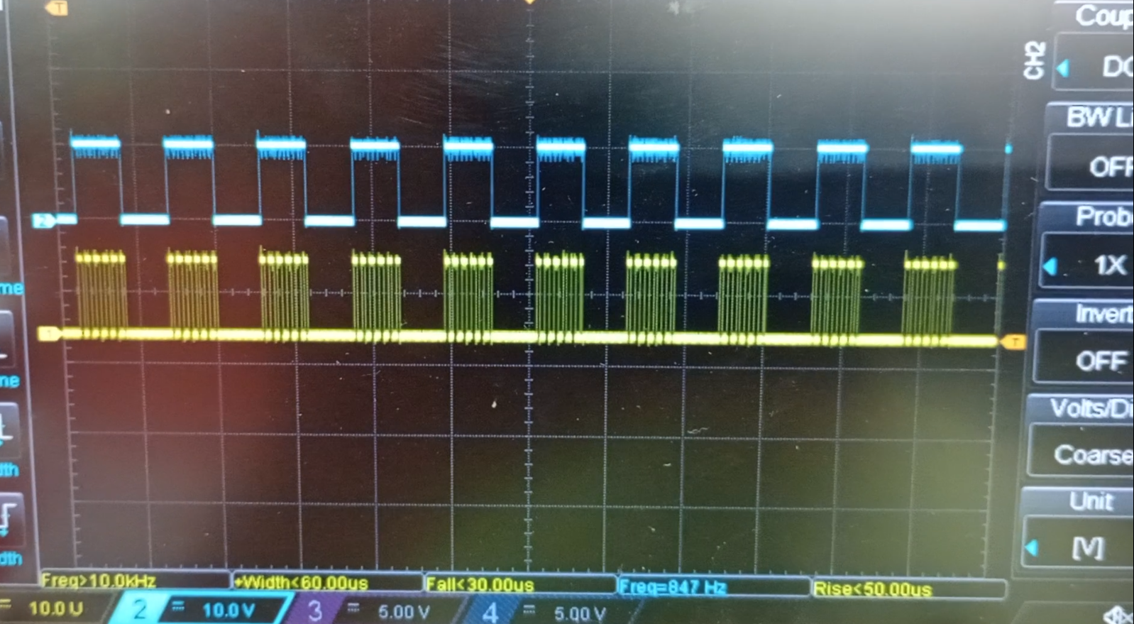
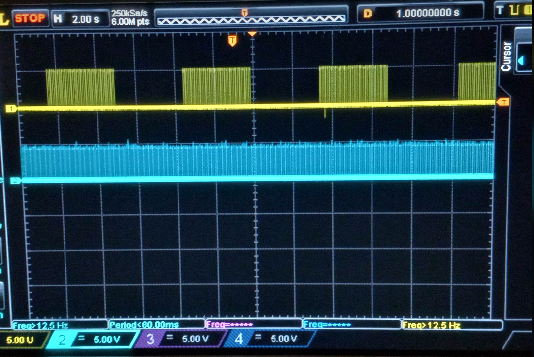
2nd setup had a modification where both signals from 555/CD4017 were fed into an 7408 AND logic gate. This produced the waveform seen below. In this instance, only 1 H11D1 optocoupler was required.
LED providing visual verification of pulse waveform.
Video Link 9XA, 7408 Mod
9XA does provide a 50% duty cycle pulse frequency with a 50% duty cycle gate frequency. However, clock drifting is an issue if both waveform generators are used independently. If both decade counter stages are driven from same 555, a synchronized clock can be achieved. It is unclear if Stan synchronized with one 555. Also, the TTL logic limits the voltage output to around 5V. CMOS version would allow higher voltages, which could drive power MOSFETs.
Adjustable Pulse Width Gated Frequency Generator
More experimentation will be conducted in the future for this method. Please check the ESP32 based generator in the VIC section for modern usages.
One can use a 555 with two 1N4148 diodes to allow independent control of duty cycle ON/OFF times. Each diode has a 100k 10-turn precision potentiometer placed in series to capacitor as shown below. Rotary switch for selection of different capacitor values can allow frequency range selectivity. "RA" below can be a potentiometer to allow for frequency adjustment.
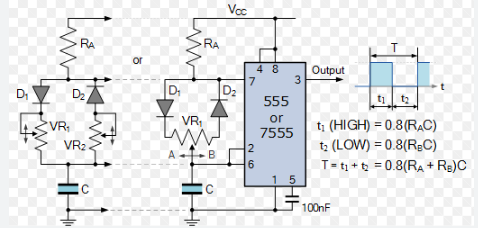
Photo from Electronic Tutorials: https://www.electronics-tutorials.ws/waveforms/555-circuits-part-1.html
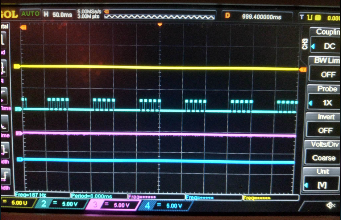
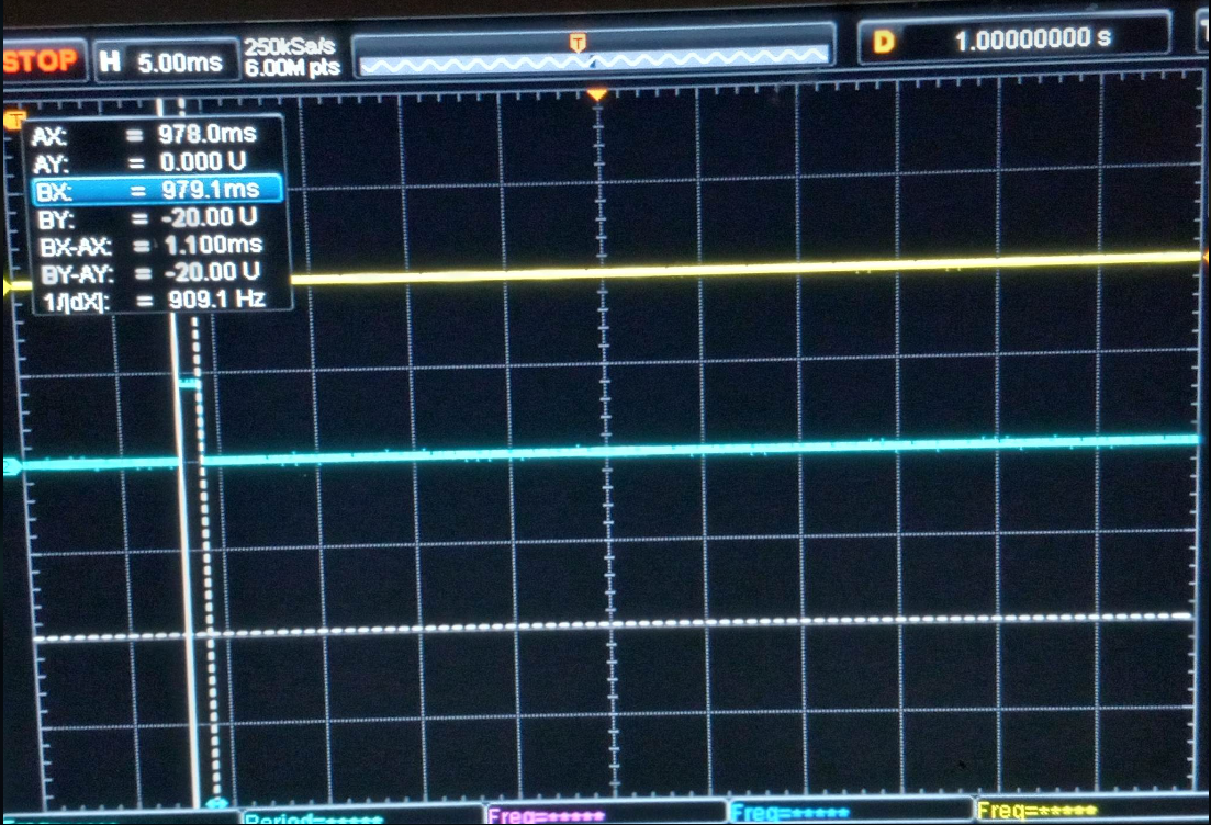
In the build below, pin 3 of 555 was also output to CD4017 decade counter stage to produce a gate. This provided clock synchronization, and only allows 5 pulses per gate ON time. Otherwise, any independent driver of CD4017 would produce clock drift and not allow a discrete number of pulse per gate ON time. Beauty of shift registers in 4017's is even though a 1mS ON time may be occurring, the whole period will be used to divide by 10. Thus maintaining a 50% gated pulse time if desired. Both the adjusted pulse train from Pin #3 and output of CD4017 (Pin #12) is put into inputs (Pin #1 and Pin #2) of a 7408 AND logic gate chip. Pin #3 on 7408 is output, which is shown in yellow below on scope. Circuit driver side isolation may be achieved with H11D1 similar to the 9XA.
Gate can be adjusted by RA resistor to produce increase occurrences of pulse train
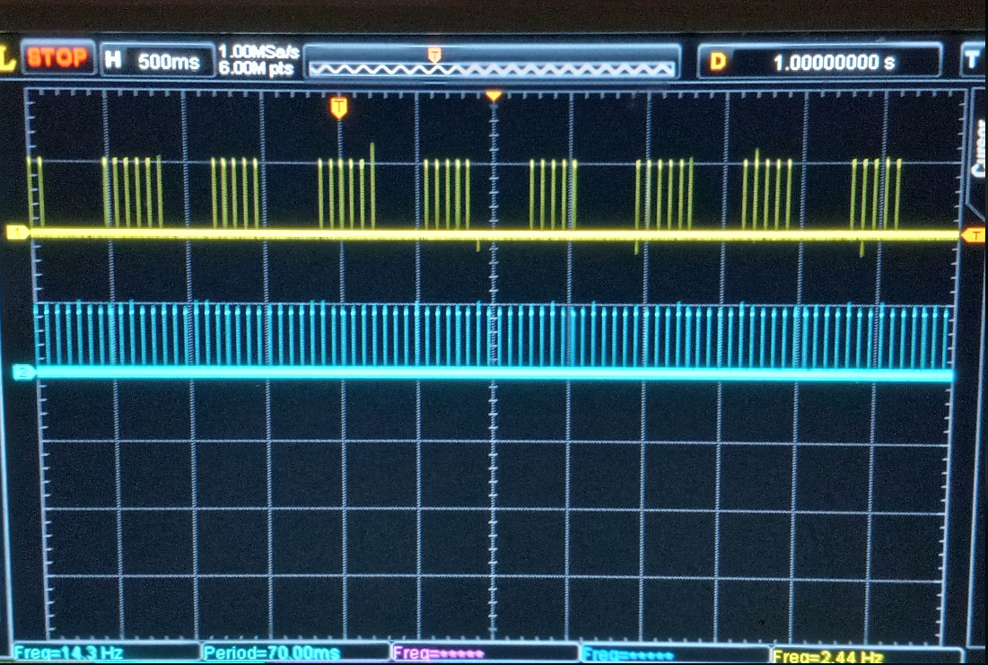
Pulse duty cycle ON time, down to lowest, measured at 1mS.
Adjustable Gated Pulse Freq Gen
This method allows pulse duty cycle control, and synchronized gate to pulse train.
9XB Generator
10XA
10XA BOX
PHYSICAL ARRANGEMENT
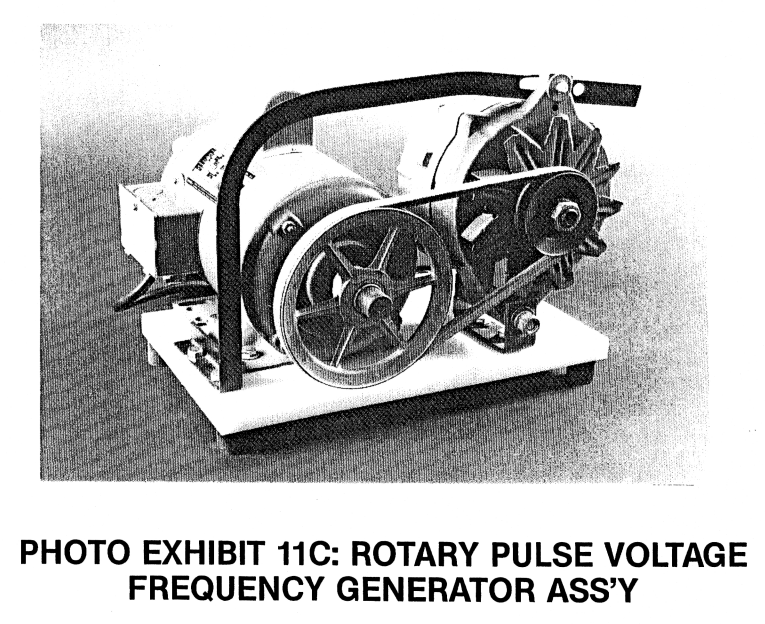
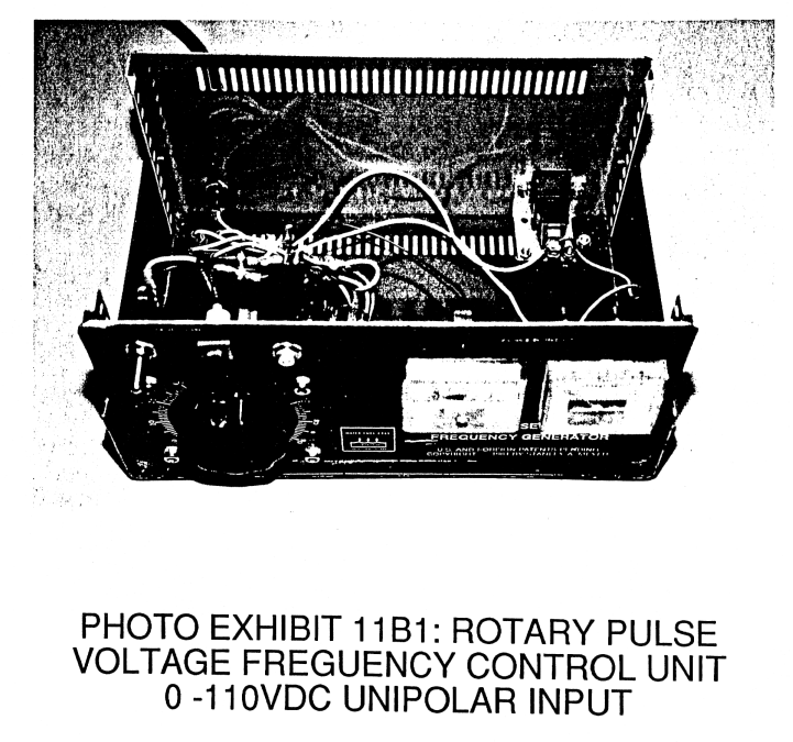
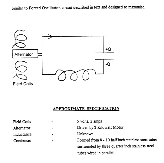
Below schematic calls out a constant speed AC motor driving a conventional-non regulated alternator. This means the alternator's internal voltage regulator and bridge rectifier diode array has been removed for Stan's desired functionality. A variable transformer is shown attached to the rotor coil of alternator to provide varying voltage. The tubing array is the demo cell. According to pictures, these tubes were wired in parallel circuit arrangement.
DEMO CELL CIRCUIT
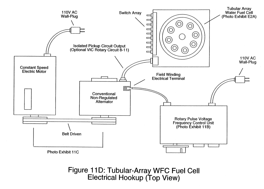
Below schematic illustrates the type of winding configuration of the alternator. In this arrangement, the alternator is in a "WYE" configuration. Each phase winding has a diode in series with it's output. The center node if the "Ground" or common reference point between all the phases. It can be seen that only 5V, rectified-unipolar DC @120Hz, is applied to the rotor. Other documentation calls out no more than 2amps. This is a total of 10watts of input power.
10XA SCHEMATIC
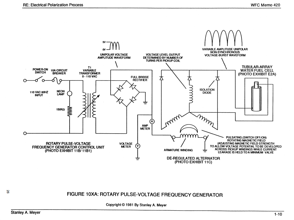
A 2kw AC motor works out to approximately 2.68HP (2000W / 746W/HP = 2.68HP). I would be ideal to use an AC motor with variable frequency drive to provide variability across a larger range. Speculating, that the rpm was 3600.
INDEPENDENT TEST REPORT PARAMETERS
CD4046 Phase Lock Loop Gated Frequency Generator
Circuit Overview
Utilizing two CD4046 Phase Lock Loop ICs and a CD4011 NAND gate to produce a gated pulse frequency waveform. One CD4046 output frequency is used to trigger the inhibit pin (pin #5) of the second CD4046, performing a "gating" function. Each frequency is based on adjustable RC time constants, frequency range being varied by selecting different capacitor values.
Circuit Schematic:
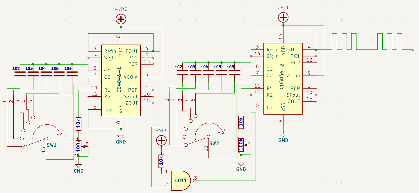
Duty cycle is fixed near 50% without the use of divide-by-ten counter ICs:
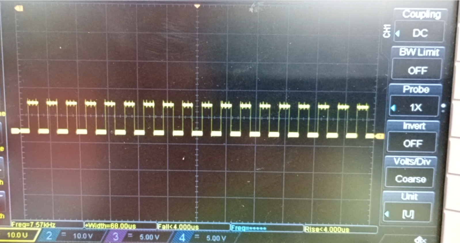
Resultant gated waveform with inhibit frequency superimposed: