10XA
10XA BOX
PHYSICAL ARRANGEMENT
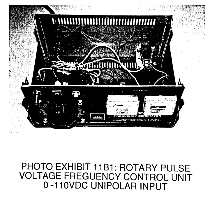
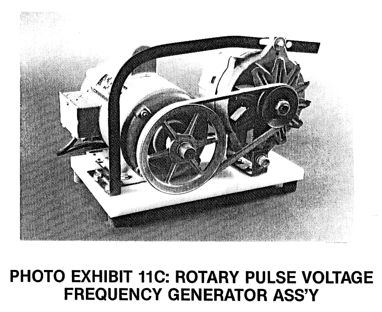
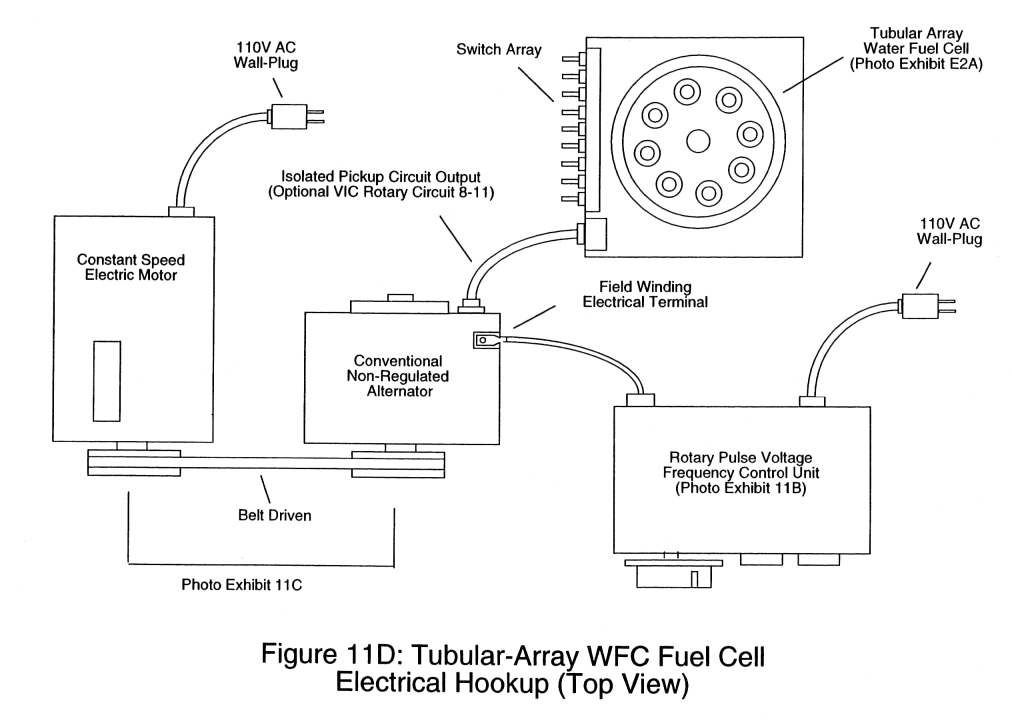
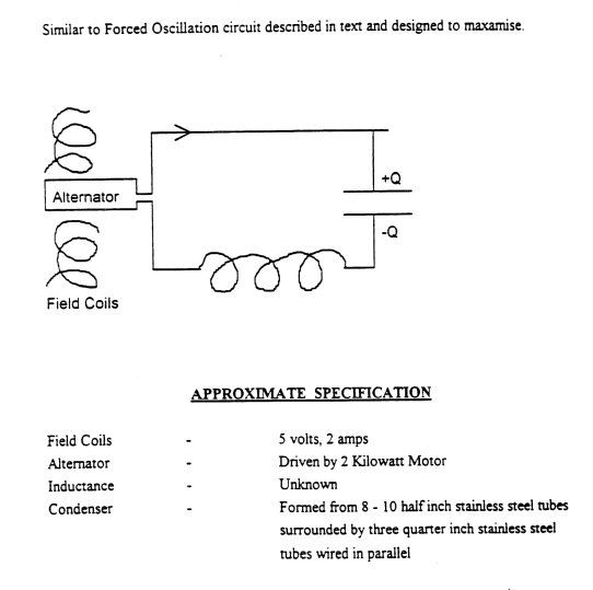
Below schematic calls out a constant speed AC motor driving a conventional-non regulated alternator. This means the alternator's internal voltage regulator and bridge rectifier diode array has been removed for Stan's desired functionality. A variable transformer is shown attached to the rotor coil of alternator to provide varying voltage. The tubing array is the demo cell. According to pictures, these tubes were wired in parallel circuit arrangement.
DEMO CELL CIRCUIT
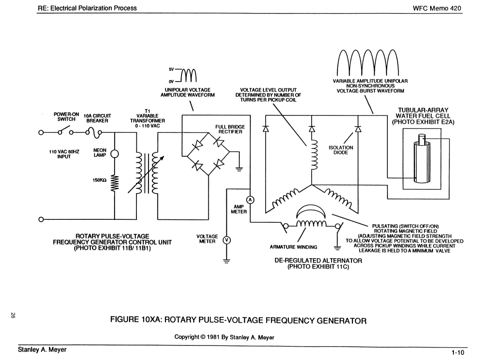
Below schematic illustrates the type of winding configuration of the alternator. In this arrangement, the alternator is in a "WYE" configuration. Each phase winding has a diode in series with it's output. The center node if the "Ground" or common reference point between all the phases. It can be seen that only 5V, rectified-unipolar DC @120Hz, is applied to the rotor. Other documentation calls out no more than 2amps. This is a total of 10watts of input power.
10XA SCHEMATIC
A 2kw AC motor works out to approximately 2.68HP (2000W / 746W/HP = 2.68HP). I would be ideal to use an AC motor with variable frequency drive to provide variability across a larger range. Speculating, that the rpm was 3600.

